•最高512 KB快閃記憶體及64 KB SRAM
•STN液晶螢幕控制/驅動功能最高可達288點。
•I2S可提供音訊處理、SSI (串列聲音介面)及SPI (串列周邊介面)通訊協定
•12位元ADC (類比至數位轉換器)含內部電壓參考以及12位元DAC (數位至類比轉換器)與溫度感應器
•完整的DSP處理功能,包括硬體式除算,可提供高效率的Sensor數位信號處理運算。
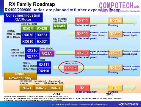
RX113 MCU同時支援互電容式與自電容式的按鍵操作偵測。電容式觸控感應單元最高支援36通道按鍵輸入(互電容模式)。相較於先前的方式,自電容式可大幅提升抗擾性及敏感度。此全新MCU亦支援瑞薩電子首次採用的互電容式,使用者戴著手套也能進行觸控操作,並具有極高的錯誤偵測抵抗性,即使觸控按鍵區域本身上面有水。電容式觸控感應單元支援厚度超過10 mm的壓克力面板,可提供彈性的設計,例如可採用曲面的面板。瑞薩已提升敏感度約五倍,可供實作非傳統表面的使用者介面(例如濕潤的面板或手套)。
RX系列可為所有使用案例提供彈性的電源管理與最佳的耗電量。32位元RX113 MCU可達到業界最高等級的電源效率,工作模式的耗電量僅0.1 mA/MHz (典型),低功率模式的耗電量僅0.44 µA (保留RAM內容)。在LCD驅動模式時亦可達到僅1.6 µA的耗電量(採用內部升壓與1/3偏壓工作模式)。
瑞薩為RX系列產品提供完整的開發生態系統,包括CS+,e2 studio、強大的Eclipse型IDE以及編譯器、除錯器、程式碼產生工具及快閃記憶體程式編輯器。RX113裝置將由廣大的RX生態系統提供支援,包含各種第三方工具、RTOS及中介軟體。目前已備妥支援IAR編譯器與IAR Embedded Workbench IDE以及Micrium RTOS與Spectrum元件。
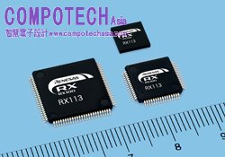
RX113 MCU目前已開始供應樣品,封裝腳位數範圍從64至100個腳位,晶片內建快閃記憶體容量範圍從128至512 KB,總計有12種個別產品。價格依據記憶體容量、封裝與腳位數而有不同。瑞薩計劃2015年2月開始量產,並預估至2016年1月合併產能可達每月1百萬顆

關於RX113 MCU之主要規格,請參考附件。
關於瑞薩電子
附件
*Upper: Temperature range for the operation:-40 to +85°C
Lower: Temperature range for the operation -40 to +105°C
|
Group name |
RX113 |
||||
|
Part No.* |
R5F51138ADxx |
R5F51137ADxx |
R5F51136ADxx |
R5F51135ADxx |
|
|
R5F51138AGxx |
R5F51137AGxx |
R5F51136AGxx |
R5F51135AGxx |
||
|
Internal memory |
Flash ROM |
512 KB |
384 KB |
256 KB |
128 KB |
|
|
RAM |
64 KB |
32 KB |
||
|
E2 data flash |
8 KB |
||||
|
Power supply voltage |
1.8 to 3.6 V |
||||
|
Maximum operating frequency |
32 MHz |
||||
|
Temperature range for the operation |
-40 to +85°C or -40 to +105°C |
||||
|
CPU core |
RX CPU
|
||||
|
On-chip peripheral functions |
Transfer functions |
Data transfer controller (DTCa) |
|||
|
|
Timers |
Multi-function timer pulse unit 2: 16 bits x 6 channels (MTU2a) Port output enable 2 (POE2a) Compare match timer (CMT): 16 bits x 2 channels x 2 units Real-time clock (RTCA) Independent watchdog timer (IWDTa): 14 bit x 1 channel 8-bit timer (TMR): (8 bit x 2 channels) x 2 units |
|||
|
|
Communication functions |
Serial communications interface (SCIe): 100-pin [7 channels], 64-pin [5 channels] Serial communications interface (SCIf): 1 channel I2C bus interface (RIIC): 1 channel Serial peripheral interface (RSPI): 1channel USB 2.0 Full Speed (USBc): [1 channel, USB 2.0 Full Speed (12 Mbps), Low Speed (1.5 Mbps) H/F/OTG] Serial sound interface (SSI): 1 channel IrDA interface: 1 channel |
|||
|
|
Touch key functions |
Capacitive Touch Sensing Unit (CTSU) x 12 channels, 36 keys (max. input keys when configuring 12 ch in the 6 ch x 6 ch matrix state using mutual-capacitance.) Self-capacitance and mutual capacitance are supported. |
|||
|
|
Analog functions |
12-bit A/D converter (S12ADb): 100-pin [17 channels], 64-pin [11 channels] 12-bit D/A converter: 2 channels (R12DAA) Comparator: 2 channels (CMPBa) |
|||
|
|
LCD controller/ driver (LCDC) |
Internal voltage boosting method, capacitor split method, and external resistance division method are switchable. Segment signal output x common signal output: 100-pin: 40 com. x 4 seg., 36 com. x 8 seg., 64-pin: 20 seg. x 4 com., 16 seg. x 8 com |
|||
|
|
Safety functions |
Clock Frequency Accuracy Measurement Circuit (CAC) Data Operation Circuit (DOC) 14 bits Independent Watchdog Timer (IWDTa) CRC Calculator (CRC) |
|||
|
|
Clock generation circuit |
Main clock oscillator Sub-clock oscillator Low-speed on-chip oscillator (LOCO) High-speed on-chip oscillator (HOCO) Dedicated on-chip oscillator for the IWDT USB-dedicated PLL frequency synthesizer USB-dedicated PLL frequency synthesizer |
|||
|
|
Others |
Event Link Controller (ELC) Multi-function Pin Controller (MPC) Power-on Reset Circuit (POR) Voltage Detection Circuit (LVD) |
|||
|
On-chip debugging function |
Yes (with trace function) |
||||
|
Low power consumption modes |
3 modes
|
||||
|
Packages |
100-pin LFQFP (PLQP0100KB-A) 14 x 14 mm, 0.50 mm pitch |
||||
SuperFlash memory technology used in Renesas Electronics' RX113 MCUs is licensed from Silicon Storage Technology Inc. SuperFlash is a registered trademark of Silicon Storage Technology in the U.S., Japan, and other countries. All other registered trademarks or trademarks are the property of their respective owners.


